The story of our off-grid solar installation — from 4 panels and a PWM controller to a full 48V energy storage system with MPPT and plans to add microinverters.
How it started — December 2020
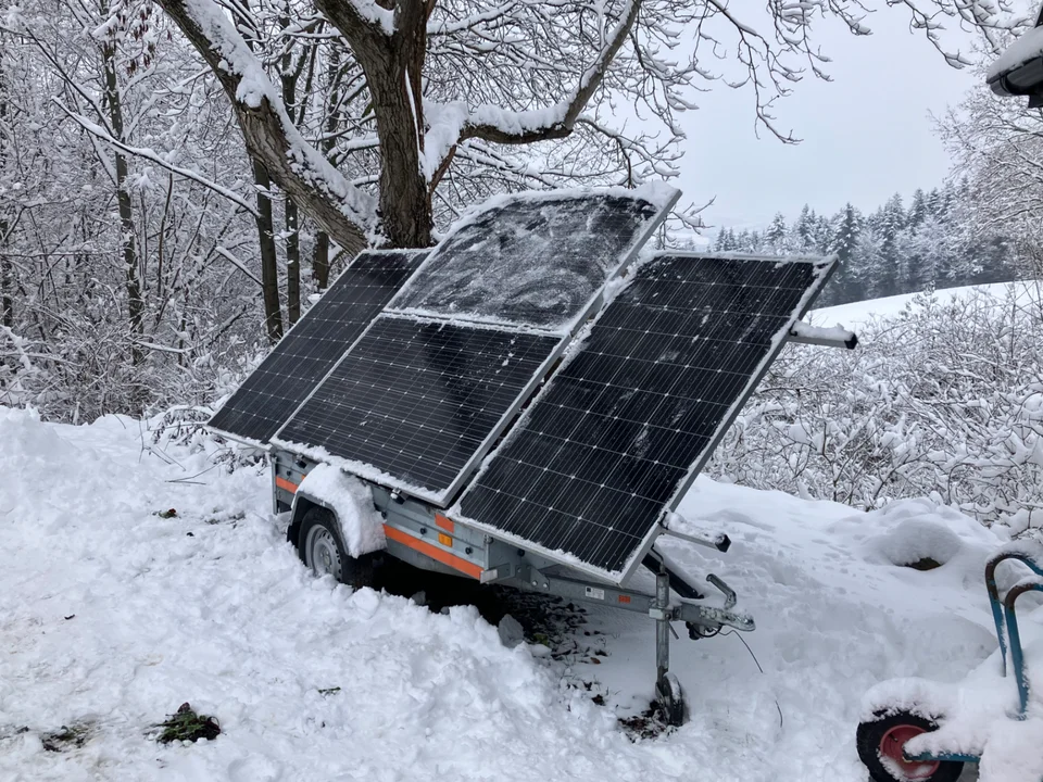
It all began with a simple goal: become energy-independent from the grid at a location where a utility connection either does not exist or is not cost-effective. At the end of 2020 we installed four monocrystalline panels at 300W each — 1200Wp of peak installed capacity in total.
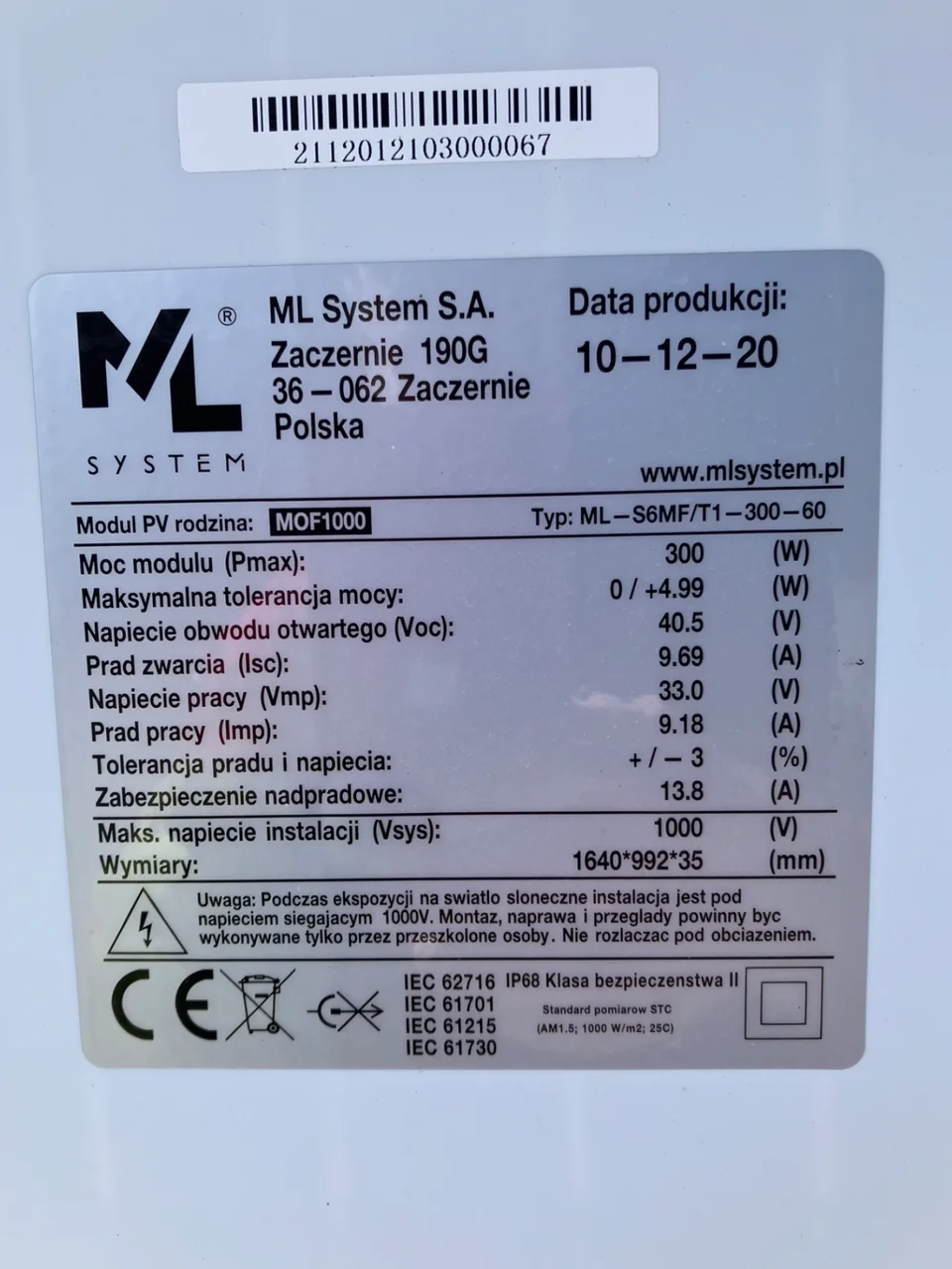
Single panel specs:
- Power: 300W
- Open-circuit voltage (Voc): 40.5V
- Operating current (Imp): 9.18A
- Operating voltage (Vmp): 33V
- Dimensions: 164×99 cm
The panels were wired in a 2S2P configuration (two series strings in parallel), giving an operating voltage of ~66V and current of ~18.4A.
Original setup — PWM controller and lead-acid batteries
The first system was simple and inexpensive. At its heart was a Chinese PWM (Pulse Width Modulation) charge controller paired with AGM (lead-acid) batteries.
A PWM controller acts like a switch — it clips panel voltage down to battery voltage. With panels at Vmp = 66V and a 48V battery bank, that means a loss of:
PWM loss = 1 − (48V / 66V) ≈ 27%
From a 1200Wp array, only ~880W actually reached the batteries at peak. The rest became heat in the controller. It was a deliberate compromise — PWM was 3–4× cheaper than MPPT, and the system worked for what we needed.
Cable infrastructure — an investment for years
Even during construction we installed a professional cable route from the panels to the building:
- Cable: 2×6mm² copper, buried underground
- Mechanical protection: flexible conduit (Arot type) along the full run
- Inspection pits: placed at key points along the route
Thanks to the conduit and pits, the cable can be swapped (thicker or additional) at any time without digging again. That turned out to be one of the best design decisions — we plan to pull an additional AC cable along the same route in the future (not necessarily in the same pipe).
At the current load (~18A DC) we do not see a significant voltage drop over the existing cable length.
Upgrade #1 — from PWM to MPPT
The first major upgrade was replacing the PWM controller with an MPPT (Maximum Power Point Tracking) unit. The difference is fundamental:
The new MPPT controller (100V Voc max, 20A charging) runs in 2S2P configuration:
- Input voltage: 81V (Voc) / 66V (Vmp) — in the optimal range
- Charging current: up to 20A at absorption voltage ~57.6V = ~1150W
- Conversion efficiency: 96–98%
Result: from the same 4 panels we get about 150–200W more at peak sun. With 5 hours of full sun that is ~750–1000 Wh more per day — for free.
Upgrade #2 — from AGM to LiFePO4
AGM lead-acid batteries have advantages (simplicity, low entry cost), but after several years of daily cycling their capacity drops sharply. We replaced them with a 48V lithium iron phosphate (LiFePO4) battery with its own BMS.
Key differences:
The BMS talks directly to the MPPT controller — when the battery is full, the controller automatically reduces charging power (curtailment). No manual configuration needed.
Upgrade #3 — full energy storage system (ESS)
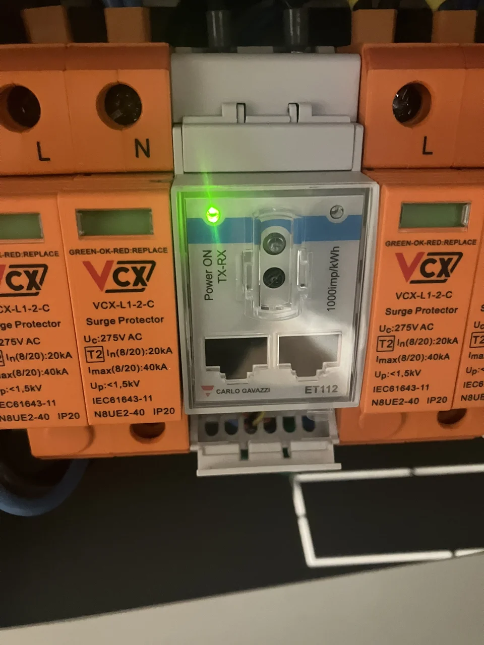
The biggest change: adding a 3kVA inverter/charger with a built-in transfer relay and a central system monitor with network connectivity.
What that gives you:
- Automatic grid/battery switchover — on a grid outage (blackout), switch to battery in <20ms
- AC-OUT — a dedicated AC network powered from the battery, independent of the utility
- Real-time monitoring — PV production, battery state, load, history
- Smart management — priority: PV surplus → battery → grid (if connected)
- Grid charging current: 35A (as backup when PV is not enough)
In the DC-coupled path (MPPT controller) the battery is charged directly — energy from the panels goes to the DC bus without DC→AC→DC double conversion. Efficiency on that path is 96–98%.
Current balance — what we have after 5.5 years
The system runs fully autonomously. In summer months (May–August) the battery reaches full charge before noon, and surplus is routed to domestic hot water heating (DHW element controlled by PV surplus automation).
What it cost — 5.5-year budget
One of the most common questions. Below is an approximate cost per stage at purchase time (Polish market):
Total system cost: ~21,600 PLN (spread over 5.5 years)
A few notes on the budget:
- PV panel prices fell ~40% since 2020 — today the same 4 panels would cost ~1,100 PLN
- A 48V 100Ah LiFePO4 battery in 2023–2024 cost ~6,000 PLN; in 2025 comparable models are ~4,500 PLN
- AGM batteries (2,000 PLN) would need replacing after 2–3 years — so LiFePO4 is effectively a saving over 10 years
- Trenching is a one-time cost — the existing route supports expansion without extra digging
- At today's electricity prices (~1 PLN/kWh) the system produces ~1,500–2,000 kWh/year = savings of 1,500–2,000 PLN per year
Payback (without grid connection costs we avoided): ~11–14 years from bill savings alone. But if you add the cost of a grid connection at this site (quote: ~25,000–35,000 PLN), off-grid is already cheaper than the grid alternative.
Expansion plans — scenarios for the future
Scenario 1: Adding AC-coupled PV (microinverters)
The main development direction. Alongside existing DC-coupled PV (MPPT controller) we add microinverters connected to the inverter AC output. Two independent battery charging sources:
DC path: Panels → MPPT → battery (direct, 96–98%)
AC path: Panels → microinverter → AC → inverter → battery (92–94%)
Benefits of hybrid DC + AC:
- Combined charging power: 20A (DC) + 35A (AC) = 55A ≈ 3.2 kW into the battery at once
- Independent curtailment: BMS controls MPPT, frequency shift controls the microinverter
- Existing cable route: AC cable can be pulled through Arot conduit without digging
- Scalable: more panels + microinverters do not require replacing anything
Planned AC-coupled power: 1600W (4 panels × ~400–500Wp on a 4-input microinverter).
After expansion: ~1.2 kW DC + 1.6 kW AC = ~2.8 kW total PV power.
Scenario 2: Longer AC run (~200m)
We are analysing running AC cable ~200m (panels at a remote point on the property). Key conclusions from the calculations:
- 3×6mm² cable over 200m gives ~3.6% voltage drop at 7A (1600W) — acceptable
- AC 230V beats DC on long runs (higher voltage = lower current = less loss)
- Surge protection (SPD) required at both ends of the cable
- Existing infrastructure (Arot conduit + pits) eliminates digging cost
Estimated cost of 3×6mm² cable alone over 200m: ~3,000–3,600 PLN.
Scenario 3: Second inverter (parallel operation)
Eventually we may add a second identical 3kVA inverter in parallel (same phase). That doubles:
- Continuous power: 2× 2.4kW = 4.8 kW
- Peak power: 2× 5.6kW = 11.2 kW (motor start-up)
- Charging current: 2× 35A = 70A from AC-coupled PV
With two inverters, Factor 1.0 rises to 3360W — allowing a second microinverter and doubling AC-coupled power.
Lessons after 5+ years of operation
- Modular approach pays off — the system grows with your budget; nothing is wasted
- Cable infrastructure is an investment — buried conduit with pits costs once and lasts decades
- MPPT vs PWM — an ~800 PLN upgrade pays back in the first year (if panels are suitable)
- LiFePO4 > AGM for cyclic use — higher price, but 5–8× longer life
- DC + AC hybrid — best of both worlds: DC for efficiency, AC for flexibility and scale
- 200m of AC cable is not a problem — 6mm² is enough, and digging cost can be avoided with existing infrastructure
Komentarze